
WINDOW ACTUATOR SELECTION GUIDE
Select the actuator around the opening and the required operation.
The correct window actuator is not selected from force or stroke alone. Opening geometry, sash size and weight, hinge or pivot arrangement, seals, required opening, mounting position, speed, synchronisation, control strategy and the way the window must behave in the building all affect the final solution.
EBSA develops the actuator, brackets, wiring and control pathway around the actual opening so the mechanical arrangement and operating sequence are resolved as one system.
The actuator follows the opening. The opening should not be redesigned around a convenient motor.
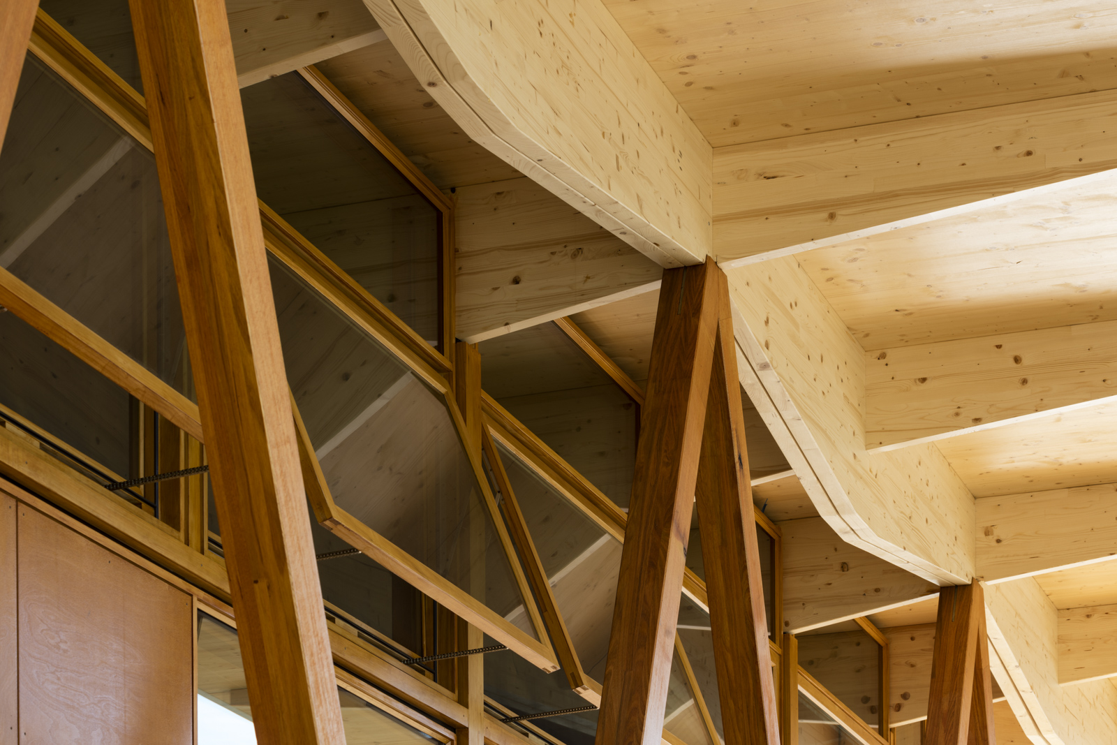
OPENING FIRST
Define what has to move before choosing how to move it.
Actuator selection begins with the complete opening condition. Two windows that appear similar in elevation can require different drive arrangements because hinge geometry, sash construction, weight distribution, seals, bracket position, available mounting space or the required movement can be different.
The first design task is therefore to define the window and the movement it must achieve. The actuator family, model, bracket and control technology follow from those requirements.
OPENING TYPE
Awning, hopper, casement, roof opening, louvre mechanism or another project-specific operable element.
HINGE / PIVOT GEOMETRY
Confirm the hinge or pivot condition and how the sash moves relative to the proposed actuator position.
SASH SIZE + CONSTRUCTION
Confirm dimensions, glazing, frame construction and other information needed to understand the opening as an operating element.
REQUIRED OPEN POSITION
Define what the project requires the opening to achieve rather than treating nominal actuator travel as the design outcome.
MOUNTING ZONE
Identify where the drive and brackets can be placed without compromising the window, facade, finishes, cable routing or future access.
OPERATING CONTEXT
Define whether the window is for day-to-day ventilation, smoke-control operation, another project-specific function or a combination of operating modes.
The opening geometry is the starting point. The actuator model is the result.
SELECTION ENGINEERING
Resolve the actuator as a sequence of connected decisions.
01 — WINDOW + OPENING GEOMETRY
02 — REQUIRED OPENING
03 — STROKE + MOVEMENT
04 — LOADS + CLOSING
05 — DRIVE POSITION + BRACKETS
06 — ACTUATOR TYPE + FAMILY
07 — SPEED + ACOUSTICS
08 — SYNCHRONISATION + FEEDBACK
09 — POWER + CONTROL
10 — TESTING + COMMISSIONING
OPENING + HINGE GEOMETRY
Establish the sash dimensions, opening direction, hinge or pivot arrangement and the relationship between the proposed actuator position and the movement of the opening.
REQUIRED OPENING
Define the final opening position or movement required by the project. Where aerodynamic or smoke-control performance depends on the opening, the requirement must come from the relevant project design rather than from the actuator catalogue.
STROKE + MOVEMENT
Actuator stroke is the travel available from the drive. Achieved window opening also depends on bracket position, geometry and the movement of the sash. Nominal stroke is therefore not the same as achieved opening.
LOADS + CLOSING
Consider the real opening and closing condition, including sash weight, seals, friction, wind or other relevant project loads, and the force transferred through the actual bracket geometry.
DRIVE POSITION + BRACKETS
Resolve the mounting zone, bracket arrangement, structure, clearances, finishes, cable route and future service access as part of the actuator decision.
ACTUATOR TYPE + FAMILY
Choose the drive principle only after the opening, movement and mounting conditions are understood. Chain, rack-and-pinion, louvre and specialist drives solve different mechanical conditions.
SPEED + ACOUSTICS
Match the required operating speed and noise expectations to the building use, control strategy and project operating sequence.
SYNCHRONISATION + FEEDBACK
Where more than one drive is required, or where additional status and configuration functions are needed, resolve the drive electronics and control architecture with the mechanical arrangement.
POWER + CONTROL
Coordinate the actuator with the selected control system so electrical load, supply arrangement, grouping, field cabling, communication and required feedback can be resolved together.
TESTING + COMMISSIONING
Confirm the installed opening operates through the intended sequence, achieves the required movement and interfaces correctly with the selected control architecture.
Actuator selection is an engineering sequence, not a model-number lookup.
DRIVE PRINCIPLE
Different opening conditions call for different actuator types.
EBSA works across multiple D+H actuation principles. The most appropriate pathway depends on the opening geometry, required movement, loads, mounting conditions, control functions and the way the element must operate within the wider building system.
CHAIN ACTUATORS
Compact and versatile actuation for a wide range of commercial windows. Different D+H chain-drive families suit different physical formats, forces, strokes, mounting arrangements, control technologies and multi-drive requirements.
RACK + PINION ACTUATORS
Robust linear actuation for opening conditions requiring a different force, travel or installation geometry from a chain drive. Final selection still depends on the complete opening and control requirement.
LOUVRE DRIVES
Purpose-designed drive pathways for automated louvre mechanisms and facade elements where movement is transferred through a coordinated louvre mechanism rather than a conventional sash arrangement.
SPECIALIST DRIVES
Locking, side-hung, door, rooflight and other specialist actuation arrangements for opening geometries that do not fit a standard chain or rack-and-pinion solution.
The drive type changes with the opening. The selection principles do not.
MOVEMENT GEOMETRY
Nominal actuator travel does not define the final window opening by itself.
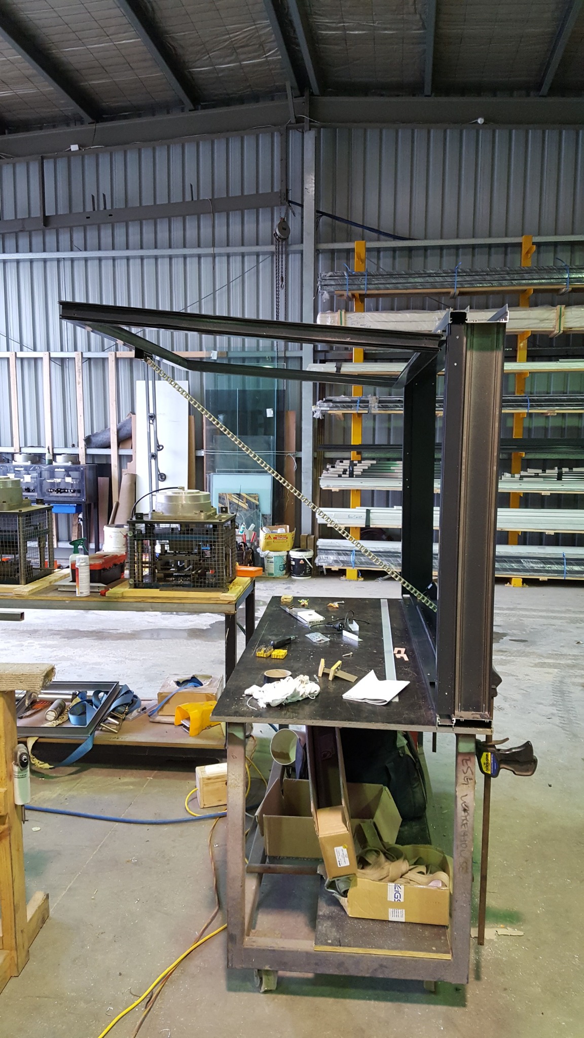
The relationship between actuator travel and achieved opening depends on the geometry of the sash, hinge or pivot, actuator position and bracket arrangement. A nominal stroke value therefore cannot be treated as a direct statement of final window angle, gap or aerodynamic opening.
The design requirement should define the movement the opening must achieve. EBSA then assesses the actuator and bracket geometry needed to produce that movement within the available facade conditions.
KEY CHECKS
• Required open position or movement
• Available actuator travel is confirmed against the current product data for the selected family and model.
• Actuator and bracket position
• Hinge or pivot location
• Clearances through the complete movement
• Potential interference with frame, glazing, hardware, blinds or facade elements
• Closing position and seal engagement
Specify the required opening outcome first. Resolve the actuator travel from there.
OPERATING LOADS
Nominal actuator force is only one part of the loading condition.
The force required to move and close an automated window is influenced by the opening geometry and by how the actuator transfers load into the sash. Window weight, seals, friction, bracket position, lever arm, frame stiffness and relevant project loads can all affect the real operating condition.
A larger nominal force rating does not automatically make an actuator suitable. The drive, brackets, sash and supporting window construction need to work together through the full movement.
• Sash weight and centre of mass where relevant
• Opening and closing geometry
• Seal compression and final closing behaviour
• Bracket leverage and load path
• Frame and sash stiffness
• Relevant project environmental loads
• Required holding, locking or closing behaviour where applicable
• Required actuator force is confirmed through project-specific assessment and checked against current product data.
The force rating belongs inside the geometry and load assessment — not outside it.
MECHANICAL INTEGRATION
The actuator and brackets are part of the window detail.
The same actuator can behave differently when its position or bracket geometry changes. The mounting arrangement influences movement, leverage, clearances, load transfer, appearance, cable entry and future access.
For commercial projects, actuator coordination should therefore happen with the window or facade system before the frame detail is frozen. EBSA reviews the available mounting zone, suitable bracket arrangements, structure, finishes, clearances, cable route and access so the automation can be incorporated cleanly into the opening.
Where profile-integrated or concealed actuation is being considered, the window system and fabricator need to be coordinated around the applicable drive geometry and installation requirements from an early stage.
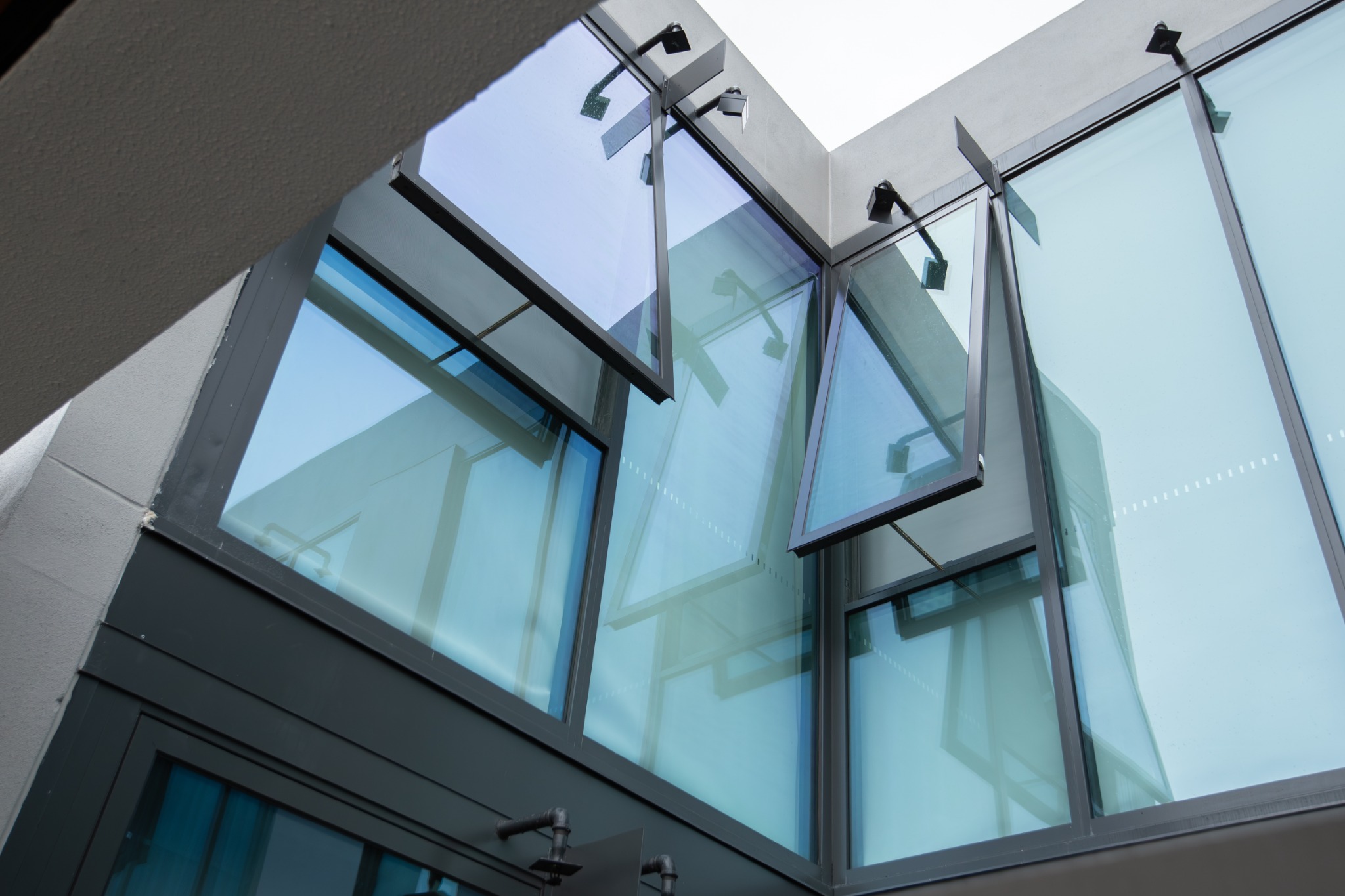
Mounting is not an accessory decision. It is part of actuator selection.
COORDINATED MOVEMENT
More actuators do not automatically create a better solution.
Window width, stiffness, load distribution, sealing and required movement can make more than one actuator appropriate on a single opening. In those applications, drive quantity and position, synchronisation technology, electrical loading, feedback and commissioning need to be developed together.
EBSA treats the complete sash as one operating element rather than treating each actuator as an independent motor. Depending on the selected drive family and control architecture, suitable synchronised, tandem or digitally addressed arrangements may be available.
The exact technology is model-dependent. Availability and functions are confirmed against the current selected D+H product.
QUESTIONS TO RESOLVE
• Can the opening be operated reliably by one drive?
• Does window stiffness or load distribution require multiple drive points?
• How will the drives be synchronised or coordinated?
• What happens if one drive is obstructed or cannot complete the commanded movement?
• What feedback or diagnostic information is required?
• How will commissioning confirm coordinated movement?