
AUTOMATED GLASS LOUVRES
Design the louvre and its operating system as one facade solution.
An automated glass louvre is more than a moving facade element. The blade architecture, operating mechanism, drive, field wiring, controls, sensors and building interfaces all need to work around the same project sequence.
EBSA connects architectural glass louvre design with D+H actuation and project-engineered control systems for natural ventilation, smoke-relief and other building operating strategies. The objective is a coordinated system from the moving glass through to BMS, mechanical and fire interfaces, commissioning and long-term support.
Facade architecture and control architecture developed together.
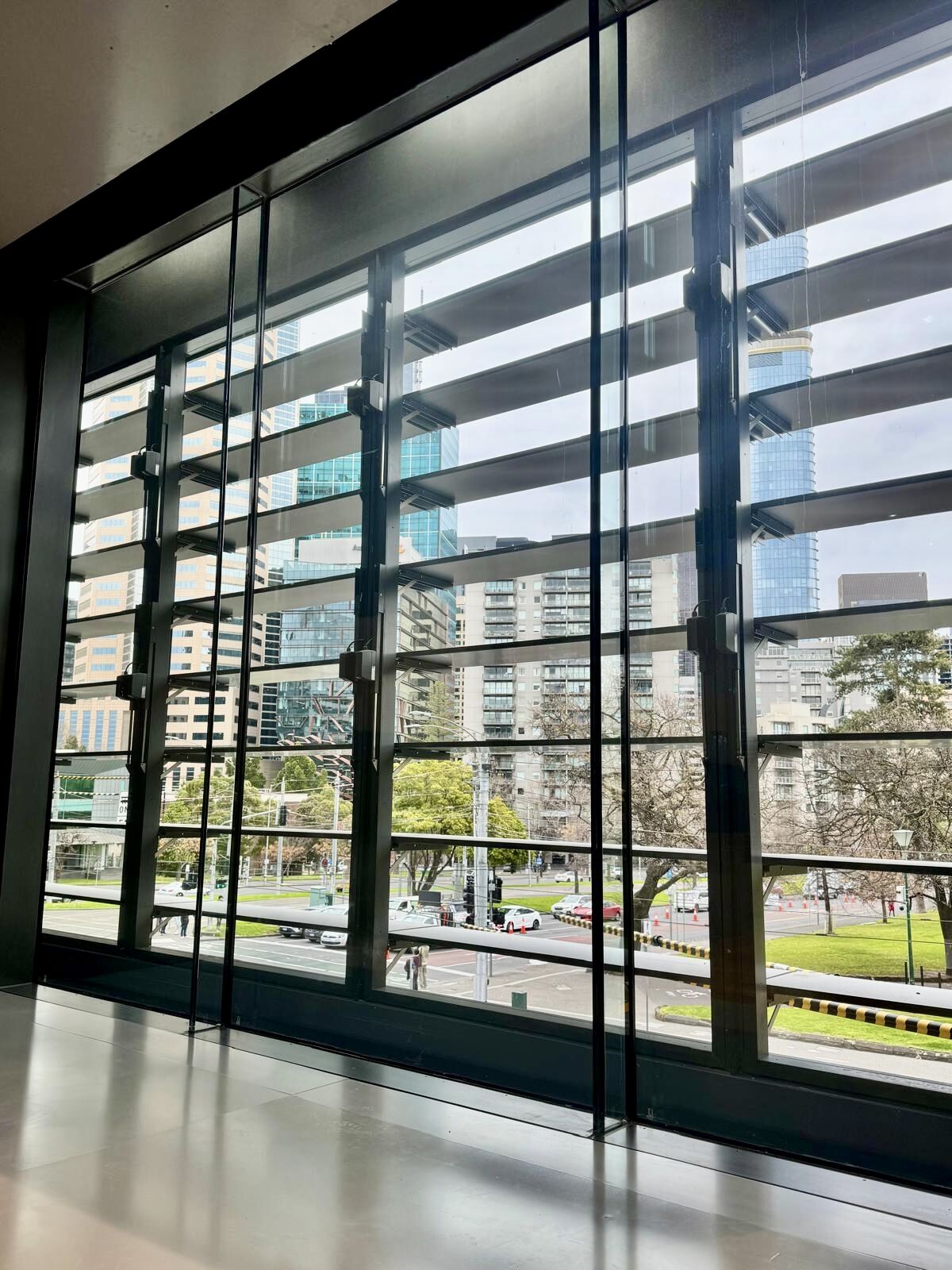
FROM GLASS BLADE TO BUILDING SYSTEM
The operating sequence should shape the system architecture from the start.
The correct automation strategy begins with what the building needs the louvre to do. That includes normal ventilation behaviour, environmental response, weather protection, user commands, zoning, status requirements, mechanical coordination, fire-system inputs and any emergency operating sequence defined by the project design.
Once those requirements are understood, the louvre mechanism, actuation, wiring and controls can be selected and coordinated around the intended movement rather than adapted after the facade is fixed.
GLASS LOUVRE
MECHANISM
DRIVE
FIELD WIRING
CONTROL SYSTEM
LOGIC + SENSORS
BMS / MECHANICAL / FIRE INTERFACES
COMMISSIONING
SERVICE
LOUVRE ARCHITECTURE
Blade size, glazing, pivot geometry, framing and facade expression determine how the louvre moves and how the operating mechanism is integrated.
MECHANISM + DRIVE
The mechanism translates actuator movement into blade movement. Drive selection must suit the actual product architecture, required movement and project operating duty.
FIELD WIRING
Power, control and monitoring wiring needs to be coordinated with drive grouping, zoning, cable routes, facade access and the selected control architecture.
CONTROL SYSTEM
The controller is selected around the application, actuator loads, groups, zones, normal and emergency functions, interfaces and required diagnostics — not around a single preferred controller family.
LOGIC + SENSORS
Environmental inputs, user commands, weather signals, timers, interlocks and project-specific sequences determine how the system behaves in normal operation.
BUILDING INTERFACES
BMS, mechanical and fire-system interfaces need defined commands, status points, priorities, overrides and responsibilities.
COMMISSIONING + SERVICE
The completed louvre is verified through its actual operating sequence, interfaces and site conditions, with the system documentation retained for future support.
The automation system is successful when the facade element and the building sequence remain connected through design, installation and commissioning.
MOVEMENT + FORCE
Select actuation around the louvre mechanism and required operation.
Different EBSA glass louvre families use different mechanical architectures. An end-pivot large-format louvre and a centre-pivot rack-and-gear louvre do not present the same movement path, load transfer or drive arrangement. Actuation therefore needs to be considered as part of the selected louvre architecture.
The public website should explain the selection logic without presenting one actuator model, force, voltage, speed or stroke as universally applicable. Those details are project-specific unless a current controlled product source expressly establishes them.
ACTUATOR / DRIVE SELECTION INPUTS
• Louvre family and mechanism.
• Blade geometry, glazing and operating arrangement.
• Required opening position and movement range.
• Operating force and mechanical efficiency of the actual assembly.
• Number of louvres or blade groups to be driven together.
• Required operating time or speed where specified.
• Normal ventilation duty and expected cycle frequency.
• Emergency sequence requirements where applicable.
• Required position feedback, monitoring or synchronisation where specified.
• Cable length, voltage drop and field-wiring arrangement.
• Accessibility for installation, adjustment and future service.
END-PIVOT / LARGE-FORMAT ARCHITECTURES
LF550 and MP2 occupy large-format end-supported / end-pivot territories. Their mechanism and actuation need to be coordinated with the substantial glass blades, vertical framing zone and project geometry. LF550 specifically uses concealed operating components within the framing zone and designed inside-face access.
CENTRE-PIVOT / CONCEALED RACK-AND-GEAR ARCHITECTURES
BT90 and G Series use centre-pivot louvre architectures with concealed rack-and-gear operation. The drive acts through the concealed mechanism rather than through visible linkage across the primary louvre face. Exact drive arrangement remains project- and product-specific.
Do not select the actuator independently of the blade and mechanism it has to move.
PROJECT-ENGINEERED CONTROLS
Build the control architecture around the required sequence of operation.
EBSA’s control-system offering is broader than one controller family. Appropriate D+H Mechatronic control options can include VCM, GVL, RZN, CPS-P, CPS-B, CPS-M and other applicable control platforms depending on the project.
The selection should begin with the engineering requirements: actuator loads, groups, zones, natural-ventilation functions, smoke or fire-sequence requirements, BMS and mechanical interfaces, weather and environmental sensing, monitoring, diagnostics and the required sequence of operation.
CPS-M is an important part of the EBSA controls capability, but it must not be presented as the only way to automate a glass louvre. Where CPS-M is selected, the stronger story is project engineering: EBSA can develop the control architecture, panel arrangement, project drawings, configuration, interfaces and commissioning around the project rather than forcing the project into a predefined control architecture.
CONTROL-ARCHITECTURE INPUTS
• Total connected drive load and distribution.
• Number of operating groups and independently controlled zones.
• Normal ventilation commands and user-control philosophy.
• Environmental inputs such as temperature, rain, wind or other specified sensors.
• Required BMS or mechanical enable / inhibit / command / status points.
• Fire-system command and priority requirements where applicable.
• Manual overrides and maintenance operation.
• Required monitoring, fault indication and diagnostics.
• Power supply and standby-power requirements defined by the project.
• Panel location, field cabling, cable routes and access.
• Commissioning, testing and handover requirements.
We do not force the project into a predefined control architecture. We engineer the control architecture around the project.
DAY-TO-DAY BUILDING OPERATION
Coordinate louvre position with the building’s ventilation and environmental strategy.
Automated glass louvres can form part of a natural-ventilation, purge or mixed-mode operating strategy. The control logic should be based on the project’s environmental and mechanical intent rather than a generic open / close command.
A typical project may require combinations of user control, BMS commands, temperature inputs, time schedules, weather response, occupancy logic, mechanical-system coordination and defined opening positions. The exact strategy must come from the project design and approved sequence of operation.
DESIGN QUESTIONS
• What condition enables natural ventilation?
• Which louvres operate together and which need separate zoning?
• Is the movement binary open / closed or are intermediate positions required?
• Which user, BMS or mechanical commands have control in normal operation?
• What weather conditions inhibit or reverse normal opening?
• How does the system respond after a weather event or loss of a normal command?
• Does mechanical plant need to enable, disable or change mode when the louvres move?
• What position feedback or status is required by the BMS?
• What manual override is required for facilities or maintenance staff?
Natural ventilation is a sequence of operation, not simply an actuator command.
PROJECT-SPECIFIC EMERGENCY OPERATION
Where louvres form part of a smoke or relief-air strategy, coordinate the complete project sequence and interfaces.
EBSA glass louvres have been used on projects where operable facade elements support smoke-relief, make-up-air or other fire-sequence functions. Those project applications demonstrate EBSA’s ability to coordinate operable louvres, actuation, controls and fire-system interfaces.
They do not create a universal smoke-control certification for every louvre family, size, actuator or arrangement. The role of the louvre must be established by the project’s fire engineering, mechanical design, specification and applicable compliance pathway.
For an emergency operating application, the system design should identify the required command source, priority, target louvre position, permitted overrides, power and monitoring requirements, interface responsibilities, reset behaviour and commissioning / witness-test requirements.
PROJECT BOUNDARIES TO DEFINE
• What function is the louvre performing in the fire or smoke strategy?
• Which project document establishes that function?
• What command initiates the sequence?
• What is the required operating position and timing?
• Which normal-ventilation commands are overridden during the emergency sequence?
• What status or fault information must be returned?
• What are the relevant power-supply and standby-power requirements?
• What fire-rated cabling or installation requirements apply to the project scope?
• Which party provides, terminates and tests each interface?
• Who witnesses and accepts the final integrated sequence?
PUBLIC CLAIM BOUNDARY
Do not describe LF550, BT90, G Series or any other louvre family as universally smoke-certified, smoke-rated or suitable for a life-safety function solely because it has been used on a smoke-relief project. Product capability, project configuration and system compliance must be assessed against the actual design.
Project proof may state the documented use: Macquarie University Law School uses BT90 louvres coordinated with CPS-M controls for natural ventilation and smoke-relief operation; Quay Quarter Tower uses a G Series application coordinated with D+H actuation and CPS-M controls as part of natural-ventilation and smoke-relief operation. These are project references, not universal certification statements.
COMMANDS, STATUS + PRIORITIES
Define the interface around the required building operation before choosing the signal method.
BMS integration is not one standard protocol or one fixed list of points. The project needs to define what the BMS is expected to command, what the louvre-control system is expected to return, which system has priority in each operating mode and how faults, overrides and emergency commands are handled.
The interface may be implemented through low-level hardwired signals, high-level communications through an appropriate controller or gateway, or a combination. The actual method and protocol are project-specific and should only be named once the selected control architecture and project requirements confirm them.
Do not assume or publish a protocol such as BACnet, Modbus or another network simply because it is common on building projects. Where a protocol is required, define the exact interface, gateway, point list and responsibility in the project documentation.
CURRENT CONTROLLED COMMUNICATION PATHWAYS
The current controlled website baseline supports low-level hardwired I/O together with high-level communication through the selected D+H control architecture. Current controlled content may reference Modbus and applicable D+H network / communication technologies including AdComNet and ACB / AdComBus, with gateway-based integration where required by the project. These are architecture options rather than a promise that every controller, drive or louvre system exposes every communication method directly. The selected controller, gateway, network topology and point list must be confirmed against the project requirements. BACnet or any other BMS protocol should only be named as a project pathway where the approved control / gateway source confirms it; do not describe it as a universal direct louvre protocol.
TYPICAL INTERFACE FUNCTIONS TO CONSIDER
• Enable / inhibit.
• Open / close or project-defined position command.
• Zone or group command.
• Normal / automatic / manual mode status.
• Open / closed / position status where the selected hardware provides it.
• General fault or defined diagnostic status.
• Weather inhibit or weather-response status where required.
• Mechanical-system interlock or mode coordination.
• Fire-system command / priority status where applicable.
• Maintenance or override status where required.
INTERFACE HIERARCHY
The sequence of operation must state which command has priority. A normal BMS ventilation request, a local maintenance override, a weather response and a project-defined fire command cannot be treated as equal requests. Priority and reset behaviour need to be explicit.
RESPONSIBILITY BOUNDARY
The specification should identify who provides the BMS / fire / mechanical signal, who provides the louvre-control interface, where the physical or network connection occurs, who supplies gateways where required, who maps points, who performs end-to-end testing and who owns changes to the final sequence.
Specify the function first. Select the interface method and protocol second.
LOUVRE ARCHITECTURE + AUTOMATION
Match the automation strategy to the selected glass louvre family.
The same controls philosophy can sit behind different louvre architectures, but the mechanism, drive arrangement, blade geometry and service access differ between product families. This matrix is a design-pathway guide, not a substitute for product-specific engineering.
MP2
Facade territory: Large-format insulated-glass architecture with thermally broken framing and end-supported / end-pivoting operation.
Automation implication: Develop actuation around the large-format end-pivot mechanism and project geometry. Use the selected control architecture for the required natural-ventilation, building-integration or project-specific sequence.
Claim boundary: Do not infer actuator model, force, opening angle, performance or emergency suitability from another louvre family or from generic MP2 positioning.
LF550
Facade territory: Large-format single-glazed frameless external expression with end-supported / end-pivoting glass blades.
Mechanism / access: Operating components are concealed within the vertical framing zone; inside-face snap-out framing provides designed access to internal components.
Automation implication: Coordinate the mechanism, drive, wiring and controls with the large glass blades, facade geometry, natural-ventilation strategy and any project-specific emergency interfaces.
Built proof: First Building, Bradfield City Centre provides a current reference for LF550 integrated with actuation and controls in a coordinated operating facade system.
Claim boundary: Do not publish a universal actuator model, force, speed, safety function or smoke certification unless confirmed by current controlled project/product information.
BT90
Facade territory: Thermally broken double-glazed / insulated-glass centre-pivot louvre architecture with a repeating framed blade expression.
Mechanism: Concealed rack-and-gear operation.
Automation implication: The selected drive acts through the concealed mechanism; controls, sensors and building interfaces are coordinated around the required project sequence.
Built proof: Macquarie University Law School provides a current BT90 reference coordinated with CPS-M controls for natural ventilation and smoke-relief operation.
Claim boundary: Product-specific actuator data, BMS protocol, smoke-control certification, universal opening angle and universal performance figures are not established by the current page-source set and must not be inferred.
G SERIES
Facade territory: Frameless single-glazed centre-pivot glass louvre family.
Configurations: Overlapping glass-on-glass or flush stepped-laminate blade expression. Mechanism: Concealed rack-and-gear operation with no visible moving linkage across the primary louvre face.
Automation implication: Coordinate the concealed mechanism and drive with blade movement, field wiring, controls and building interfaces around the project sequence.
Built proof: Quay Quarter Tower provides a current G Series reference at the podium skylight, coordinated with D+H actuation and CPS-M controls as part of natural-ventilation and smoke-relief operation.
Claim boundary: Exact actuator model, force, speed, feedback, BMS protocol, fire interface and smoke-control certification remain project-specific / unverified unless a current controlled source establishes them.
Product family is selected from the facade requirement first. Automation is then engineered around the selected louvre architecture and the building’s required operation.
INFORMATION REQUIRED TO ENGINEER THE SYSTEM
A useful automation specification describes the facade, the required movement and the building sequence.
The earlier the project team provides the key design inputs, the earlier EBSA can resolve the correct louvre, actuation and control architecture and identify interface gaps before they become site issues.
FACADE + LOUVRE DATA
• Louvre family or required architectural design territory.
• Overall louvre width and height.
• Blade geometry, glass strategy and operating arrangement.
• Quantity and location of louvres.
• Facade orientation and relevant exposure conditions.
• Surrounding curtain wall, cladding, structure and perimeter interface.
• Required access for installation, adjustment, cleaning and service.
OPERATING REQUIREMENTS
• Normal open / closed / modulating requirement.
• Required groups and zones.
• Desired or specified operating time where relevant.
• Normal cycle frequency / duty expectation.
• Required intermediate positions if applicable.
• Manual operation / override requirements.
• Status and fault requirements.
NATURAL-VENTILATION INPUTS
• BMS or standalone control philosophy.
• User commands.
• Temperature / environmental inputs.
• Rain / wind / weather response.
• Time schedules or occupancy conditions.
• Mechanical-system interlocks.
SMOKE / FIRE-SEQUENCE INPUTS WHERE APPLICABLE
• Fire engineering or mechanical design basis.
• Required louvre function.
• Command source.
• Required emergency position.
• Priority over normal operation.
• Required operating time.
• Power / standby-power criteria.
• Cable and installation requirements.
• Status, monitoring and reset requirements.
• Integrated test / witness requirements.
BMS + CONTROLS DATA
• Required point list.
• Hardwired versus high-level interface preference or project requirement.
• Required protocol only where specified.
• Gateway responsibilities where applicable.
• Network / addressing responsibilities.
• Required feedback and alarm points.
• Location of control panels and interface panels.
• BMS, mechanical, electrical, fire and facade scope boundaries.
DOCUMENTATION
• Approved sequence of operation.
• Project-specific shop drawings.
• Control schematics and point schedules where applicable.
• Cable / termination information.
• Interface matrix.
• Commissioning and test records.
• Handover information for the final installed system.
Good automation starts with a clear operating brief, not with a controller model number.
ONE OPERATING FACADE
Keep facade, electrical, controls and building-services responsibilities connected through delivery.
Automated louvres cross traditional trade boundaries. The facade contractor may own the physical opening and perimeter, electrical scope may provide power or field cabling, mechanical or BMS contractors may provide commands, fire contractors may provide emergency inputs, and the louvre-control system must make all of those interfaces behave as one operating system.
The coordination task is therefore as important as the hardware selection.
FACADE COORDINATION
Resolve louvre geometry, blade clearances, perimeter detail, drainage, tolerances, mechanism space, actuator / drive access and maintenance access with the completed facade condition.
ELECTRICAL COORDINATION
Define incoming supplies, field-cabling routes, cable types, segregation, terminations, panel locations and any project-specific fire-rating requirements.
CONTROLS COORDINATION
Define groups, zones, sensors, commands, priorities, feedback, fault behaviour, manual overrides and panel / controller architecture.
BMS + MECHANICAL COORDINATION
Agree the point schedule, command direction, status return, operating modes, interlocks, interface type and commissioning responsibilities.
FIRE-SYSTEM COORDINATION
Where a fire or smoke sequence applies, confirm the command source, priority, emergency state, reset and end-to-end integrated testing against the approved project design.
SHOP DRAWINGS + DOCUMENTATION
Use project-specific documentation to communicate the actual louvre arrangement, system architecture and interfaces rather than relying on generic product sheets to define site responsibilities.
The complete system needs one coordinated sequence even when several trades contribute to it.
VERIFY THE INSTALLED SEQUENCE
Commission the louvre through the same interfaces the building will use.
Commissioning should verify more than individual blade movement. The completed system needs to be checked from command through to final louvre response, including relevant status, interlocks, environmental inputs, BMS / mechanical interfaces and any project-defined emergency sequence.
COMMISSIONING PATHWAY
01 — MECHANICAL CHECK
Confirm louvre movement, clearances, adjustment, mechanism operation and final installed condition.
02 — DRIVE + FIELD WIRING
Verify drive operation, direction, grouping, terminations and the field-wiring configuration against the project documentation.
03 — CONTROL FUNCTION
Verify controller configuration, groups, zones, local commands, sensors, logic and required manual operation.
04 — BUILDING INTERFACES
Test BMS, mechanical and fire-system inputs / outputs that form part of the EBSA scope or agreed integrated test plan.
05 — SEQUENCE OF OPERATION
Run the approved normal and project-specific emergency sequences through the actual installed system.
06 — STATUS + FAULTS
Confirm required feedback, alarms, faults and override indication where the selected hardware and project design require them.
07 — HANDOVER
Provide the agreed project documentation, commissioning records and operating information so future service work can start from the as-commissioned system rather than rediscovering it.
Lifecycle note
Serviceability and access should be considered during design. Concealed mechanisms still need a defined inspection, adjustment and maintenance path within the finished facade.
CLAIM + DESIGN CONTROL
Apply the correct standard and evidence to the actual project function and configuration.
An automated louvre can involve facade-performance requirements, electrical and controls requirements, natural-ventilation objectives and, on some projects, smoke or fire-sequence obligations. Those are related but not interchangeable compliance questions.
FACADE PERFORMANCE
Air, water, structural and other facade-performance evidence should be read against the tested or assessed louvre configuration. Do not turn one product specimen or one project into a universal rating for every size, glazing arrangement or perimeter condition.
AUTOMATION
Actuator and control selection must suit the actual louvre mechanism, electrical design, operating duty and required sequence. Do not publish generic actuator performance as a universal louvre-system value.
NATURAL VENTILATION
Natural-ventilation operation must follow the project’s mechanical / environmental design and approved control philosophy.
SMOKE / FIRE APPLICATIONS
Where a louvre is part of a smoke-relief, make-up-air or other fire-related sequence, the project design must establish the function, required position, timing, interfaces, power requirements and compliance pathway. A previous project application is evidence of experience, not a blanket certification.
BMS / PROTOCOLS
No one communication protocol applies to every EBSA louvre project. Use the interface and protocol required by the selected control architecture and project specification. Do not invent network support or gateway capability in public copy.
PRODUCT LIMITATIONS
Do not publish universal maximum sizes, opening angles, drive forces, glass limits, free-area values, BMS protocols, emergency operating times, safety functions or warranty periods unless they are verified by the current controlled product and project source appropriate to that claim.
PUBLICATION CONTROL
Technical, fire, smoke-control, certification, performance and integration claims require EBSA review before production publication. Keep unresolved technical controls internal rather than filling the public page with defensive disclaimers or guessed values.
AUTOMATION IN BUILT FACADES
See how different louvre architectures connect into building operation.
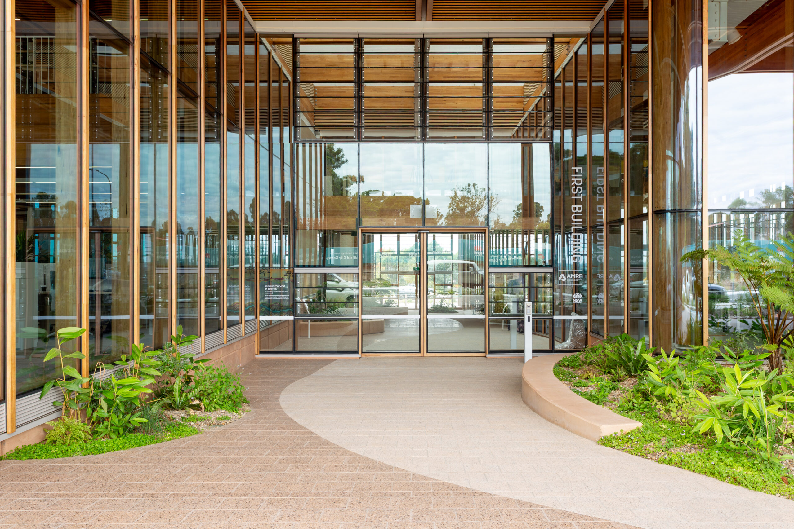
FIRST BUILDING — BRADFIELD CITY CENTRE
System territory: LF550 large-format frameless glass louvres. Proof point: LF550 integrated with actuation and controls as part of a coordinated operable facade system. Use: Demonstrates the bridge between large-format architectural louvres, concealed operation and building controls.
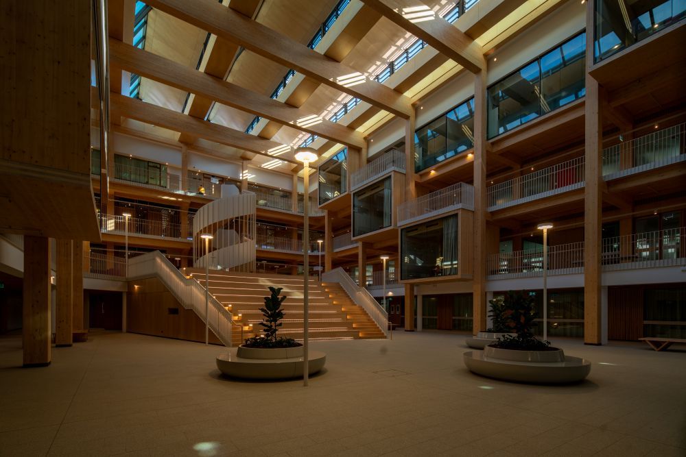
MACQUARIE UNIVERSITY LAW SCHOOL — SYDNEY
System territory: BT90 thermally broken double-glazed centre-pivot louvres. Proof point: BT90 coordinated with CPS-M controls for natural ventilation and smoke-relief operation. Use: Demonstrates a centre-pivot insulated-glass louvre connected to a project-specific operating and emergency sequence.
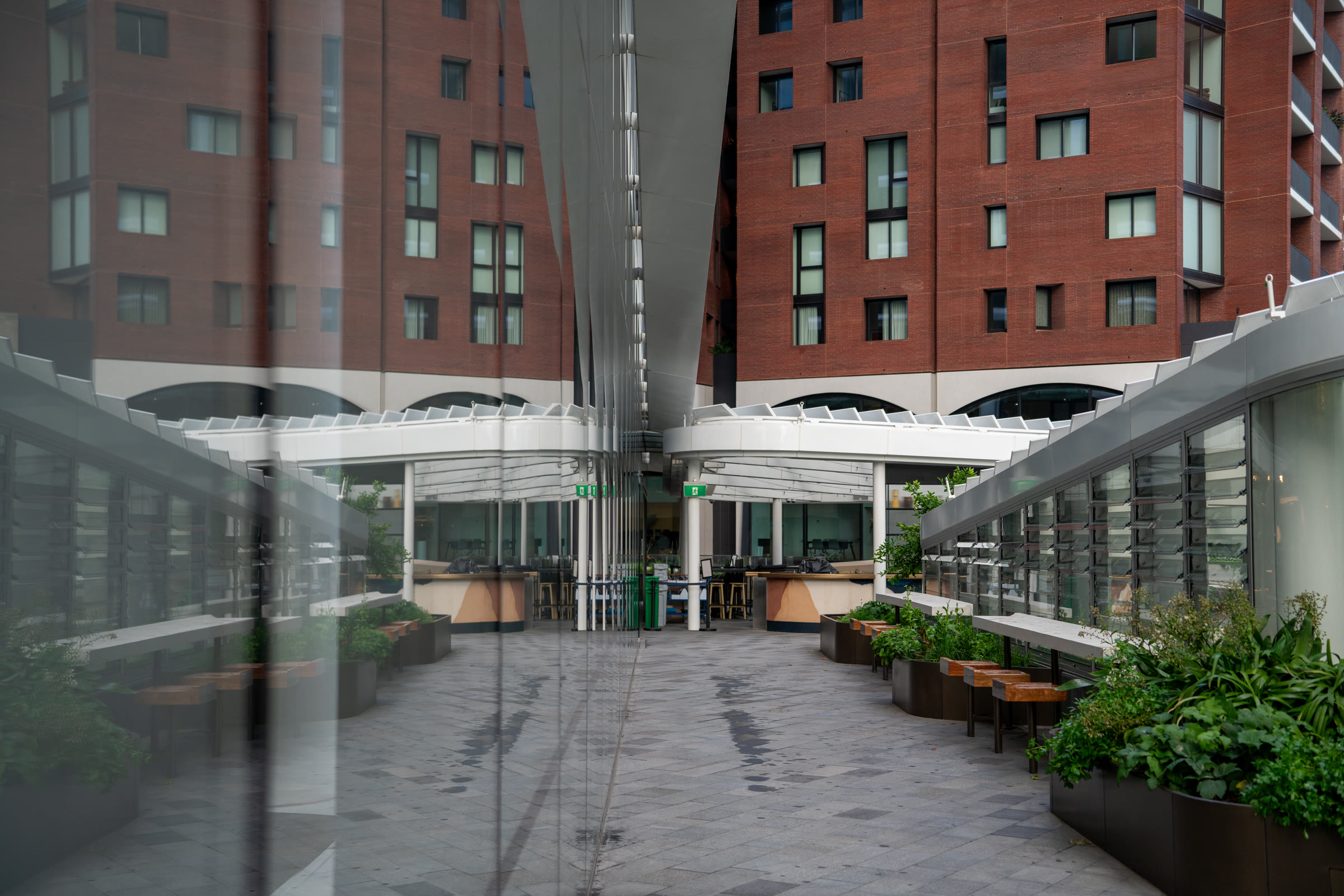
QUAY QUARTER TOWER — SYDNEY
System territory: G Series frameless centre-pivot louvres at the podium skylight. Proof point: G Series coordinated with D+H actuation and CPS-M controls as part of natural-ventilation and smoke-relief operation. Use: Demonstrates concealed louvre operation integrated with the wider building strategy.
Automated glass louvre FAQs
Can glass louvres be connected to a BMS?
Yes, where the selected control architecture provides the required interface. The project should define the commands, status points, priorities and interface method first. The actual low-level or high-level connection and any protocol / gateway requirement are then engineered around that brief.
Does EBSA use one controller for every automated louvre project?
No. EBSA works with the appropriate broader D+H control range, including VCM, GVL, RZN, CPS-P, CPS-B, CPS-M and other applicable options. Selection depends on the actuator loads, groups, zones, natural-ventilation and smoke / fire requirements, BMS interfaces, sensing, diagnostics and project sequence.
Is CPS-M the standard solution for all automated glass louvres?
No. CPS-M is a major project-engineered platform within EBSA’s controls capability, but it is not the only control solution. It is selected where its modular architecture suits the project requirements.
Can automated glass louvres be used for natural ventilation?
Yes. Automated louvres can form part of natural-ventilation, purge or mixed-mode strategies where the louvre geometry, actuation, controls, sensors and building sequence are coordinated around the project design.
Can EBSA glass louvres be used for smoke control?
EBSA louvre systems have been used on projects where operable facade elements support smoke-relief or related fire-sequence functions. Suitability is project-specific. The fire / mechanical design must establish the louvre function, required operation, interfaces and compliance pathway; a previous project use is not a universal product certification.
Do BT90 and G Series use visible operating linkages?
Their current approved product positioning uses concealed rack-and-gear operation. BT90 is a framed centre-pivot double-glazed pathway; G Series is a frameless centre-pivot single-glazed pathway with overlapping or flush blade expressions.
How is LF550 automated?
LF550 uses an end-supported / end-pivoting large-format architecture with operating components coordinated within the vertical framing zone. The drive and controls are selected around the actual project geometry and operating requirements, with designed inside-face access to concealed components.
Can one BMS command control all louvres?
It can be possible for a BMS to issue a common command, but the correct grouping and zoning depend on facade orientation, space use, ventilation strategy, mechanical operation, weather response and any emergency sequences. The control design should define zones from the building requirement rather than assume one global group.
What information should be provided for design?
Provide the proposed louvre type and geometry, quantity, facade condition, required opening behaviour, groups / zones, normal ventilation sequence, sensors, BMS / mechanical points, any fire-related function, power / cabling information and the required commissioning / handover scope.
Who coordinates the BMS, fire and mechanical interfaces?
The project responsibilities must be explicitly defined. EBSA can engineer the louvre-control side and coordinate the required interfaces, but the specification and interface matrix should identify who provides each command, cable, gateway, termination, point mapping and integrated test.
Does automation need to be considered before the louvre is selected?
The facade requirement should lead product selection, but automation requirements need to be introduced early. Required blade movement, control zones, service access, weather logic, BMS / fire interfaces and wiring can all affect the final louvre and facade detail.
AUTOMATED LOUVRE PROJECT APPLICATION
Bring the facade intent and operating sequence to EBSA early.
If the project team can provide the intended glass louvre architecture, geometry, facade condition, natural-ventilation or smoke-relief function, control zones, BMS / mechanical / fire interfaces and required sequence of operation, EBSA can develop the actuation and control pathway around the project.